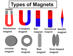
Types of Magnetism
Ampere Force
Charged bodies are capable of creating, in addition to electricity, another kind of field. If the charges move, a special kind of matter is created in the space around them, called the magnetic field. Consequently, the electric current, which is an ordered movement of charges, also creates a magnetic field. Like the electric field, the magnetic field is not limited in space, it propagates very quickly, but still with a finite velocity. It can be detected only by the action of moving charged bodies (and, as a result, currents).
To describe the magnetic field, it is necessary to introduce a force characteristic of the field, similar to the electric field intensity E. Such a characteristic is the magnetic induction vector B. In the SI system of units, 1 Tesla (T) is taken as the unit of magnetic induction. If in a magnetic field with induction B we place a conductor of length l with current I, then a force will act on it, called the Ampere force, which is calculated by the formula:
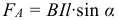
where: B is the magnetic induction, I is the current in the conductor, and l is its length. Ampere force is directed perpendicular to the vector of magnetic induction and the direction of the current flowing through the conductor.
To determine the direction of the Ampere force, the “Left hand” rule is usually used: if the left hand is positioned so that the induction lines enter the palm and the outstretched fingers are directed along the current, then the retracted thumb will indicate the direction of the Ampere force acting on the conductor (see figure ).
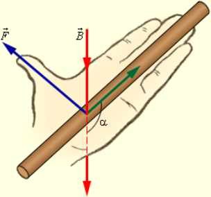
If the angle α between the directions of the vector of magnetic induction and current in a conductor is different from 90 °, then to determine the direction of the Ampere force, it is necessary to take a component of the magnetic field, which is perpendicular to the direction of the current. Solving the problems of this topic should be the same as in the dynamics or statics, i.e. writing the forces along the axes of coordinates or adding forces according to the rules of vector addition.
The moment of the forces acting on the frame with the current
Let the frame with the current is in a magnetic field, and the frame plane is perpendicular to the field. Ampere forces will compress the frame, and their result will be zero. If you change the direction of the current, the Ampere force will change its direction, and the frame will not shrink but will stretch. If the magnetic induction lines lie in the plane of the frame, then the rotational moment of the Ampere forces arises. The rotational moment of the Ampere force is:

where: S is the frame area, α is the angle between the normal to the frame and the magnetic induction vector (the normal is a vector perpendicular to the plane of the frame), N is the number of turns, B is the magnetic field induction, I is the current in the frame.
Lorenz force
The Ampere force acting on a segment of a conductor of length Δ l with a current strength I located in a magnetic field can be expressed in terms of the forces acting on individual charge carriers. These forces are called Lorentz forces. The Lorentz force acting on a particle with charge q in a magnetic field B, moving with velocity v, is calculated by the following formula:
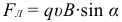
The angle α in this expression is equal to the angle between the velocity and the magnetic induction vector. The direction of the Lorentz force acting on a positively charged particle, as well as the direction of the Ampere force, can be found by the left-hand rule or by the gimlet rule (as is the Ampere force).
You need to mentally thrust the vector of magnetic induction into the palm of your left hand, direct four closed fingers along the speed of movement of the charged particle, and a bent thumb will show the direction of the Lorentz force. If the particle has a negative charge, then the direction of the Lorentz force, found by the rule of the left hand, will have to be replaced by the opposite.
The Lorentz force is directed perpendicular to the velocity and magnetic field induction vectors. When a charged particle moves in a magnetic field, the Lorentz force does not perform work. Therefore, the modulus of the velocity vector during particle motion does not change. If a charged particle moves in a uniform magnetic field under the action of a Lorentz force, and its velocity lies in a plane perpendicular to the magnetic field induction vector, then the particle will move in a circle, the radius of which can be calculated using the following formula:

The Lorentz force in this case plays the role of a centripetal force. The period of revolution of a particle in a uniform magnetic field is equal to:

The latter expression shows that for a given mass of charged particle m circulation period (and therefore the frequency, and the angular velocity) is independent of speed (and hence the kinetic energy) and the radius of the trajectory R.
Magnetic field theory
Magnetic interaction currents
If a current flows in one direction along two parallel wires, then they are attracted; if in opposite directions, then repel. The patterns of this phenomenon were experimentally established by Ampere. The interaction of currents is caused by their magnetic fields: the magnetic field of one current acts on the Ampere force of another and vice versa.
Experiments have shown that the modulus of the force acting on a segment of length Δ l of each of the conductors is directly proportional to the current I 1 and I 2 in the conductors, the length of the segment Δ l and inversely proportional to the distance R between them:
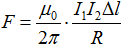
where: μ 0 – constant, which is called the magnetic constant. The introduction of the magnetic constant in the SI simplifies the writing of a number of formulas. Its numerical value is:
μ 0 = 4 π · 10 –7 H / A 2 ≈ 1.26 · 10 –6 H / A 2 .
Comparing the expression just given for the interaction force of two conductors with a current and the expression for the Ampere force, it is easy to get an expression for the induction of a magnetic field created by each of the straight conductors with a current at a distance R from it:

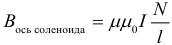
where: μ is the magnetic permeability of the substance (more on this below). If the current flows through a circular coil, then in the center of the coil the magnetic induction is determined by the formula:

The force lines of the magnetic field are the lines along which the magnetic arrows are tangent. A magnetic arrow is called a long and thin magnet, its poles are dotted. The magnetic needle suspended on a thread always turns in one direction. In this case, one of its ends is directed toward the north, the second – to the south. Hence the name of the poles: north ( N ) and south ( S ).
Magnets always have two poles: the north (indicated by blue or the letter N ) and the south (in red or the letter S). The magnets interact in the same way as the charges: like poles repel each other, while opposite ones attract each other. It is impossible to get a magnet with one pole. Even if the magnet is broken, then each part will have two different poles.
Magnetic induction vector
The magnetic induction vector is a vector physical quantity that is a characteristic of the magnetic field, numerically equal to the force acting on a current element of 1 A and a length of 1 m if the direction of the power line is perpendicular to the conductor. It is designated In, a unit of measure – 1 Tesla. 1 T is a very large value, therefore in real magnetic fields, magnetic induction is measured in mT.
The vector of magnetic induction is directed tangentially to the power lines, i.e. coincides with the direction of the north pole of the magnetic needle placed in this magnetic field. The direction of the magnetic induction vector does not coincide with the direction of the force acting on the conductor, so the magnetic field lines, strictly speaking, do not force lines.
The magnetic field line of the permanent magnets is directed toward the magnets themselves as shown in the figure:

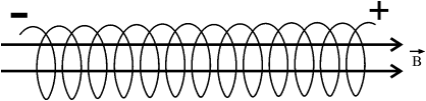
In the case of a magnetic field of electric current, the “Right Hand” rule is used to determine the direction of the power lines: if you take a conductor in your right hand so that your thumb is directed along the current, four fingers that encircle the conductor show the direction of the power lines around the conductor:

In the case of direct current, the magnetic induction lines are circles whose planes are perpendicular to the current. Magnetic induction vectors are tangential to a circle.
The solenoid is a conductor wound on a cylindrical surface through which electric current flows. I. The magnetic field of the solenoid is similar to the field of a direct permanent magnet. Inside a solenoid of length l and the number of turns N, a uniform magnetic field is created with induction (its direction is also determined by the right-hand rule):
Magnetic field lines have the form of closed lines – this is a common property of all magnetic lines. This field is called a vortex. In the case of permanent magnets, the lines do not terminate on the surface, but penetrate inside the magnet and close inside. This distinction between electric and magnetic fields is explained by the fact that, unlike electric fields, magnetic charges do not exist.
Magnetic properties of matter
All substances have magnetic properties. The magnetic properties of a substance are characterized by relative magnetic permeability μ, for which the following is true:

This formula expresses the correspondence of the magnetic field induction vector in a vacuum and in this medium. In contrast to the electric, magnetic interaction with the medium to be observed and the amplification and attenuation of the interaction compared to a vacuum, in which the magnetic permeability μ = 1.
In diamagnetic materials the magnetic permeability μ slightly less than unity. Examples: water, nitrogen, silver, copper, and gold. These substances somewhat weaken the magnetic field. Paramagnetic — oxygen, platinum, magnesium — slightly enhance the field, having μ a little more than one. In ferromagnetic materials – iron, nickel, cobalt – M >> 1. For example, iron M ≈ 25,000.
Magnetic flux. Electromagnetic induction
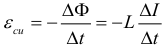
The phenomenon of electromagnetic induction was discovered by the outstanding English physicist M. Faraday in 1831. It consists of the occurrence of an electric current in a closed conductive loop when the magnetic flux penetrating the loop varies with time. Magnetic flux Φ through the area S contour is called the value:
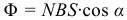
where: B is the modulus of the magnetic induction vector, α is the angle between the magnetic induction vector B and the normal (perpendicular) to the contour plane, S is the contour area, and N is the number of turns in the contour. The unit of magnetic flux in the SI system is called Weber (WB).
Faraday experimentally established that when a magnetic flux changes in a conducting circuit, induction emf ε ind appears, equal to the rate of change of magnetic flux through the surface bounded by a circuit taken with a minus sign:

A change in the magnetic flux penetrating a closed loop can occur for two possible reasons.
- The magnetic flux changes due to the movement of the contour or its parts in a time-constant magnetic field. This is the case when the conductors, and with them, the free charge carriers, move in a magnetic field. The emergence of the induced emf is due to the action of the Lorentz force on free charges in moving conductors. The Lorentz force plays in this case the role of external force.
- The second reason for the change in the magnetic flux penetrating the circuit is the time variation of the magnetic field when the circuit is stationary.
When solving problems, it is important to immediately determine how the magnetic flux changes. Three options are possible:
- The magnetic field is changing.
- The contour area is changing.
- Changing the orientation of the frame relative to the field.
In this case, when solving problems, they usually consider the emf in the module. We also pay attention to one particular case in which the phenomenon of electromagnetic induction occurs. So, the maximum value of the induced emf in a circuit consisting of N turns, an area S, rotating with an angular velocity ω in a magnetic field with induction B :

Conductor movement in a magnetic field
When a conductor with a length l in a magnetic field B moves at a speed of v at its ends, a potential difference arises, caused by the action of the Lorentz force on free electrons in the conductor. This potential difference (strictly speaking, EMF) is found by the formula:
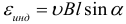
where: α is the angle that is measured between the direction of the velocity and the magnetic induction vector. In the fixed parts of the circuit, EMF does not occur.
If a rod of length L rotates in a magnetic field B around one of its ends with an angular velocity ω, then a potential difference (EMF) arises at its ends, which can be calculated by the formula:

Inductance. Self-induction. Magnetic field energy
Self-induction is an important special case of electromagnetic induction when a varying magnetic flux causing an induced emf is generated by a current in the circuit itself. If the current in the circuit under consideration changes for some reason, then the magnetic field of this current changes, and, consequently, the own magnetic flux penetrates the circuit.
An emf of self-induction arises in the circuit, which, according to the Lenz rule, prevents a change in the current in the circuit. The intrinsic magnetic flux Φ that penetrates a circuit or a coil with a current is proportional to the strength of current I :

The coefficient of proportionality L in this formula is called the coefficient of self-induction or inductance of the coil. The unit inductance in the SI is called Henry (G).
Remember: the inductance of the circuit does not depend on the magnetic flux, or on the current in it, but is determined only by the shape and size of the circuit, as well as the properties of the environment. Therefore, when the current in the circuit changes, the inductance remains unchanged. The inductance of the coil can be calculated by the formula:

where: n – the concentration of turns per unit length of the coil:

The EMF of self-induction arising in a coil with a constant inductance value, according to the Faraday formula, is equal to:
So self-induced emf is directly proportional to the inductance of the coil and the rate of change of current in it.
The magnetic field has energy. Just as in a charged capacitor there is a supply of electrical energy, in a coil, through which the current flows, there is a supply of magnetic energy. The energy W m of the magnetic field of a coil with inductance L, generated by current I, can be calculated using one of the formulas (they follow each other with the formula Φ = LI ):

Correlating the formula for the energy of the magnetic field of a coil with its geometrical dimensions, you can obtain a formula for the bulk density of the energy of the magnetic field (or energy per unit volume):

Lenz rule
Inertia is a phenomenon that occurs in mechanics (when a car accelerates, we deviate backward, counteracting an increase in speed, and when braking we deviate forward, counteracting a decrease in speed), and in molecular physics (when a fluid heats up, the evaporation rate increases, the fastest molecules leave the fluid, reducing heating rate) and so on.
In electromagnetism, inertia manifests itself in counteracting a change in the magnetic flux penetrating the circuit. If the magnetic flux increases, the induction current arising in the circuit is directed so as to prevent the increase of the magnetic flux, and if the magnetic flux decreases, then the induction current arising in the circuit is directed so as to prevent the magnetic flux from decreasing.
Lens rule for determining the direction of the induction current: the induction current arising in the circuit has such a direction that the magnetic field created by it prevents the magnetic flux that caused this current to change.


