What is optics in physics?
optics, science concerned with the genesis and propagation of light, the changes that it undergoes and produces, and other phenomena closely associated with it. There are two major branches of optics, physical and geometrical. Physical optics deals primarily with the nature and properties of light itself.
Basic Laws of Optics:
Optics is the branch of physics that deals with light, its properties, and applications. This post explained the basics of optics, its properties, and the Basic laws of optics. This post also includes:
- Optics Definition
- Types of Optics
- Laws of Optics
- Interference of light
- Diffraction of light
- Spherical lenses
- Mirrors
- much more
This is a bit more complicated than the basics. You see, there are two laws that are essential to understanding optics. The first one is the Law of Reflection, which mainly regulates how mirrors act, and the second is the Law of Refraction. All that is explained on this page is referred to as lenses.
Keep reading …
Light waves
Light is electromagnetic waves, the wavelengths of which lie for the average human eye in the range from 400 to 760 nm. Within these limits, the light is called visible. Light with the longest wavelength appears to us red, and with the smallest – purple. Remember alternating colors of the spectrum easily using the sayings ” By azhdy About hotnik F elaet Hnat, Mr. de With idit F adhan.”
The first letters saying the words correspond to the first letters of the primary colors of the spectrum in order of decreasing wavelength (and therefore increasing frequency): ” To the Red LED – About Ranjeva – FYellow LED – WJelenia – D oluboy – With iny – F ioletovy “. Light with larger than red wavelengths is called infrared. His eye does not notice, but our skin captures such waves in the form of thermal radiation. Light with shorter wavelengths than violet is called ultraviolet.
Electromagnetic waves (and, in particular, light waves, or just light ) is an electromagnetic field propagating in space and in time. Electromagnetic waves are transverse – the electric intensity and magnetic induction vectors are perpendicular to each other and lie in a plane perpendicular to the direction of wave propagation. Light waves, like any other electromagnetic waves, propagate in a substance with a finite velocity, which can be calculated by the formula:

where: ε and μ are the dielectric and magnetic permeabilities of the substance, ε 0 and μ 0 are electric and magnetic constants: ε 0 = 8.85419 · 10 –12 F / m, μ 0 = 1.25664 · 10 –6 GN / m. The speed of light in a vacuum (where ε = μ = 1) is constant and equal to с = 3 ∙ 10 8 m / s, it can also be calculated by the formula:
The speed of light in a vacuum is one of the fundamental physical constants. If the light propagates in any environment, then the speed of its propagation is also expressed by the following relationship:

where: n is the refractive index of a substance — a physical quantity that shows how many times the speed of light in a medium is less than in a vacuum. The refractive index, as can be seen from the previous formulas, can be calculated as follows:

- Light carries energy. When light waves propagate, a stream of electromagnetic energy arises.
- Light waves are emitted in the form of individual quanta of electromagnetic radiation (photons) by atoms or molecules.
In addition to light, there are other types of electromagnetic waves. Then they are listed by decreasing the wavelength (and, accordingly, by increasing the frequency):
- Radio waves;
- Infrared radiation;
- Visible light;
- Ultraviolet radiation;
- X-ray radiation;
- Gamma radiation.
Interference
Interference is one of the clearest manifestations of the wave nature of light. It is associated with the redistribution of light energy in space when applying the so-called coherent waves, that is, waves having the same frequency and constant phase difference.
The intensity of light in the region of beam overlap has the character of alternating light and dark stripes, and at the maxima, the intensity is greater and at the minima less than the sum of the intensities of the beams. When using white light, interference fringes turn out to be colored in different colors of the spectrum.
The concept of optical path length is used to calculate the interference. Let the light pass the distance L in a medium with a refractive index n. Then its optical path length is calculated by the formula:

Interference requires the imposition of at least two rays. For them, the optical path difference (optical length difference) is calculated using the following formula:
It is this value that determines whether the interference will occur: minimum or maximum. Remember the following: the interference maximum (light band) is observed in those points in space where the following condition is fulfilled:

The phase difference of the oscillations in this case is:

When m = 0, a zero-order maximum is observed, with m = ± 1, a first-order maximum, and so on. The interference minimum (dark band) is observed when the following condition is met:
The phase difference of the oscillations in this case is:

At the first odd number (one) there will be a minimum of the first order, at the second (three) a minimum of the second order, etc. Minimum zero-order does not happen.
See Also: Magnetism
Diffraction. Diffraction grating
Diffraction of light is the phenomenon of deviation of light from the rectilinear direction of propagation when passing near obstacles whose dimensions are comparable to the wavelength of light (light bending around obstacles). As experience shows, under certain conditions, light can enter the region of a geometric shadow (that is, to be where it should not be).
If there is a circular obstacle on the path of the parallel light beam (a circular disk, a ball, or a circular hole in an opaque screen), then a diffraction pattern appears on the screen at a sufficiently large distance from the obstacle – a system of alternating light and dark rings. If the obstacle is linear (slit, thread, screen edge), then a system of parallel diffraction bands appear on the screen.
Diffraction gratings are periodic structures engraved with a special dividing machine on the surface of a glass or metal plate. In good lattices, the strokes parallel to each other have a length of the order of 10 cm, and for every millimeter, there are up to 2000 strokes. In this case, the total length of the lattice reaches 10–15 cm.
The manufacture of such lattices requires the use of the highest technologies. In practice, coarser gratings with 50–100 strokes per millimeter deposited on the surface of a transparent film are also used.
With a normal incidence of light on the diffraction grating in some directions (besides the one in which the light initially fell), maxima are observed. In order to observe the interference maximum, the following condition must be met:

where: d is the period (or constant) of the grating (the distance between adjacent strokes), and m is an integer, which is called the order of the diffraction maximum. In those points of the screen for which this condition is fulfilled, the so-called principal maxima of the diffraction pattern are located.
The laws of geometric optics
Geometrical optics is a branch of physics in which the wave properties of light are not taken into account. The basic laws of geometric optics were known long before the physical nature of light was established.
An optically homogeneous medium is the medium in the whole volume of which the refractive index remains unchanged.
The law of rectilinear propagation of light: in an optically homogeneous medium, light propagates rectilinearly. This law leads to the notion of a light beam as a geometric line along which light propagates.
It should be noted that the law of rectilinear propagation of light is violated and the concept of a light beam loses its meaning if the light passes through small holes, whose dimensions are comparable with the wavelength (in this case diffraction is observed).
At the interface between two transparent media, light can be partially reflected so that a part of the light energy will spread after reflection in a new direction, and partially pass through the border and spread in the second medium.
The law of reflection of light: the incident and reflected rays, as well as perpendicular to the interface between two media, restored at the point of incidence of the beam, lie in the same plane (the plane of incidence). The angle of reflection γ is equal to the angle of incidence α. Note that all angles in optics are measured from the perpendicular to the interface between two media.
The law of refraction of light (Snell’s law): incident and refracted rays, as well as perpendicular to the interface of two media, restored at the point of incidence of the beam, lie in the same plane. The ratio of the sine of the angle of incidence α to the sine of the angle of refraction β is a value constant for these two media, and is determined by the expression:

The law of refraction was experimentally established by the Dutch scientist V. Snellius in 1621. The constant value n 21 is called the relative refractive index of the second medium relative to the first. The refractive index of the medium relative to the vacuum is called the absolute refractive index.
An environment with a large value of the absolute index is called optically denser, and with a smaller one, less dense. When moving from a less dense medium to a more dense beam, it is “pressed” to the perpendicular, and when moving from a denser to less dense, it “moves” away from the perpendicular. The only case where the beam is not refracted is if the angle of incidence is 0 (that is, the rays are perpendicular to the interface).
When light passes from an optically more dense medium to an optically less dense n 2 < n 1 (for example, from glass to air), one can observe the phenomenon of total internal reflection, that is, the disappearance of the refracted ray. This phenomenon is observed at angles of incidence exceeding a certain critical angle α apr , which is called the limiting angle of total internal reflection.
For the angle of incidence α = α pr , sin β = 1, since β = 90 °, this means that the refracted ray goes along the interface itself, while, according to Snell’s law, the following condition is satisfied:

As soon as the angle of incidence becomes greater than the limiting one, the refracted ray no longer simply goes along the border, but it does not appear at all, since its sine must now be greater than one, and this cannot be.
Lenses
A lens is a transparent body bounded by two spherical surfaces. If the thickness of the lens itself is small compared with the radii of curvature of spherical surfaces, then the lens is called thin.
Lenses are collecting and scattering. If the refractive index of the lens is greater than the environment, then the collecting lens in the middle is thicker than at the edges, the diffusing lens, on the contrary, is thinner in the middle part. If the refractive index of the lens is less than the environment, then the opposite is true.
The straight line passing through the centers of curvature of spherical surfaces is called the main optical axis of the lens. In the case of thin lenses, we can approximately assume that the main optical axis intersects with the lens at one point, which is commonly called the optical center of the lens.
The beam of light passes through the optical center of the lens, not deviating from the original direction. All lines passing through the optical center are called side optical axes.
If a beam of rays parallel to the main optical axis is directed at the lens, then after passing through the lens, the rays (or their continuation) will gather at one point F, which is called the main focus of the lens. A thin lens has two main focuses, symmetrically located relative to the lens on the main optical axis. In collecting lenses tricks are real, in scattering ones they are imaginary.
The distance between the optical center of the lens O and the main focus F is called the focal length. It is denoted by the same letter the F.
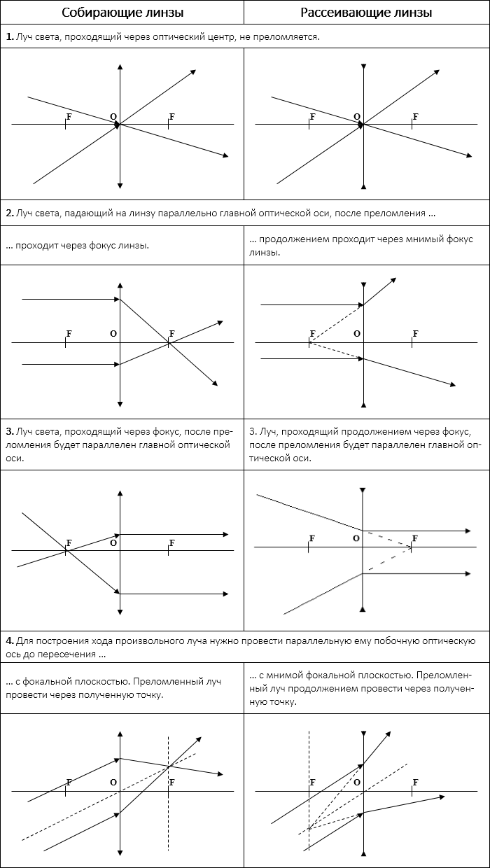
Rules for constructing the course of the beam in the lenses
Lens formula
The main property of lenses – is the ability to give images of objects. The image is the point of space where the rays (or their continuations) emitted by the source after refraction in the lens intersect. Images are direct and inverted, real (the rays themselves intersect) and imaginary (continuations of the rays intersect), enlarged and reduced.
The position of the image and its character can be determined using geometric constructions. To do this, use the properties of some standard rays, the course of which is known. These are the rays passing through the optical center or one of the lens foci, as well as rays parallel to the main or one of the secondary optical axes.
For simplicity, you can remember that the image of a point will be a point. The image of a point lying on the main optical axis lies on the main optical axis. The image of the segment – the segment. If the segment is perpendicular to the main optical axis, then its image is perpendicular to the main optical axis. But if the segment is tilted to the main optical axis at a certain angle, then its image will be tilted at some other angle.
Images can also be calculated using a thin lens formula. If the shortest distance from the object to the lens is denoted by d, and the shortest distance from the lens to the image by f, then the formula of a thin lens can be written as:
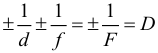
The value of D, is the reverse focal length. called the optical power of the lens. The unit of measurement of optical power is 1 diopter (diopter). Diopter – the optical power of the lens with a focal length of 1 m.
Focal lengths of lenses are usually assigned certain signs: for a collecting lens F > 0, and for a diffusing F <0. The optical power of the diffusing lens is also negative.
The values of d and f also obey a certain rule of signs: f > 0 for real images; f <0 – for imaginary images. Before d, the sign “-” is placed only in the case when a converging beam of rays falls on the lens. Then they are mentally extended to the intersection behind the lens, an imaginary light source is placed there, and the distance d is determined for it.
Depending on the position of the object in relation to the lens, the linear dimensions of the image change. The linear increase in the lens Γ is the ratio of the linear dimensions of the image and the object. For a linear increase in the lens there is a formula:

In many optical devices, light successively passes through two or more lenses. The image of the object given by the first lens serves as the object (real or imaginary) for the second lens, which builds the second image of the object and so on.


