We explain what is the technical drawing and the types of technical drawing that are made. Also, what are the lines you use.
-
What is technical drawing?
The technical drawings is a branch of the drawing known as the system that graphically represents one or more objects , in order to provide useful information for a possible and consequent analysis that will allow for the next construction and maintenance of the object.
Technical drawings is the graphic language used to communicate , within the framework of industrial and design activities, from the most global ideas to details linked to technological content.
The technical drawings has also been defined as the system of graphic representation of existing objects or prototypes, according to standards and conventions pre-established by regulatory institutions. This allows describing precisely and clearly the dimensions, shapes and characteristics of these material objects .
It should be noted that the idea of technical drawing is often in opposition to that of artistic drawing . While the first is intended to express impressions or personal sensations, influenced by the imagination and individual experiences, so it is eminently subjective, the technical drawing aims to be objective and represent the best possible objects as they are, in a totally objective way, in order to provide any observer with the technical information necessary for its technical analysis, eventually helping its design, construction and / or maintenance.
Regarding the history of technical drawing, we cannot fail to mention the first Greek mathematicians such as Thales, Pythagoras and Euclid, who laid the foundations of the so-called space geometry, fundamental in this discipline . During the Renaissance , the contributions of Brunelleschi and the famous and multifaceted Leonardo da Vinci stand out.
The diagrams , sketches, the diagrams and drawings are embodiments containing technical drawing specifications for length measurements of height, angles , surface, etc . The basic views in the technical drawing are the plan view (top view), the elevation, which can be the front or side; and that of sections or cuts in two projections. The definition of scales helps the interpretation of these representations.
-
Types of technical drawing
Within the technical drawings some specific types are included, such as:
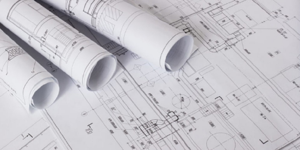
- Architectural technical drawing It includes different graphic representations, which serve to make plans for the future construction of buildings, houses, bridges, institutes, etc.
- Mechanical technical drawings Its use is required for the realization of plans that represent parts of a machine, cars, airplanes, motorcycles and industrial machinery.
- Electrical technical drawing It serves to represent simple electrical installations, such as those of a dwelling, or rather complex, such as those of an industry. The latter usually clearly represent the location of the main board, of the switches and power sockets, among others.
- Geological technical drawings Used in the fields of geology and geography for the representation of the various layers of the earth through a symbology that allows to know the minerals found in that layer.
- Urban drawing It is used to represent in a functional way the development and infrastructure of cities and other urban centers, both those already existing or those that are in the project stage.
- Topographic drawing It is dedicated to capture in a plane the main characteristics of a land, such as height, slope, the presence of natural or artificial accidents, dimensions, contours.
- Technical drawing of sanitary facilities. It aims to represent all sanitary facilities: bathroom, shower, sink, etc. It also represents the location of external and internal pipes.
- Electronic technical drawing It is based on the representation of electronic graphics and drawings of current circulation circuits.
- Technical drawing of metal constructions. Represents plans for the constructionof blacksmith structures .
The technical drawing can be translated into different media (paper, acetate, passe-partout ) , and is usually carried out on a board, with the help of elements such as rule T, square, bevel, tiralinear, compass, marker. Through the development of programs such as AutoCAD, for example, computer science has contributed greatly to the development of technical drawing.
-
Lines used in the technical drawing

Within the branch of the technical drawing appears the line, a fundamental characteristic of it, important to illustrate the different objects. There are, then, different types of lines, among the main ones are:
- Guide line It is used to indicate a part of the object to which a note refers.
- Break line Used in order to represent a long piece which is shortened.
- Hidden Line Segmented lines that represent corners or vertices of objects that are hidden from perception.
- Flat cutting line It is used to represent where an imaginary cut was made.